
1 Overview
What GravityFlow is, and what it can do for you.
GravityFlow is a design tool for branched (tree-shaped) water supply networks — the kind used for rural and small-town schemes that carry water from a hillside intake or reservoir (or, with an optional pump, a borehole or low-lying source) down to tapstands. You draw the network directly on a satellite map, and GravityFlow instantly tells you whether every pipe and every tapstand will actually get water at a safe pressure and a healthy velocity.
Map-based design
Draw sources, tanks, junctions and pipes directly on real satellite or topographic imagery.
Instant hydraulics
Hazen‑Williams headloss, HGL, pressure and velocity — recalculated the moment you hit Calculate.
Built-in design checks
Automatic warnings for low pressure, high velocity, loops, and BPTs that won't fill.
Feasibility & costing
Check your source can meet demand over a design horizon, then generate a priced Bill of Quantities.
Real files, real ownership
Your project lives in a plain JSON file on your own computer — open it, save it, take it with you.
Professional reports
Print a full design report, a standalone BOQ, or a feasibility report — ready to hand to a client or funder.
2 Core Concepts
The building blocks every GravityFlow network is made from.
Source
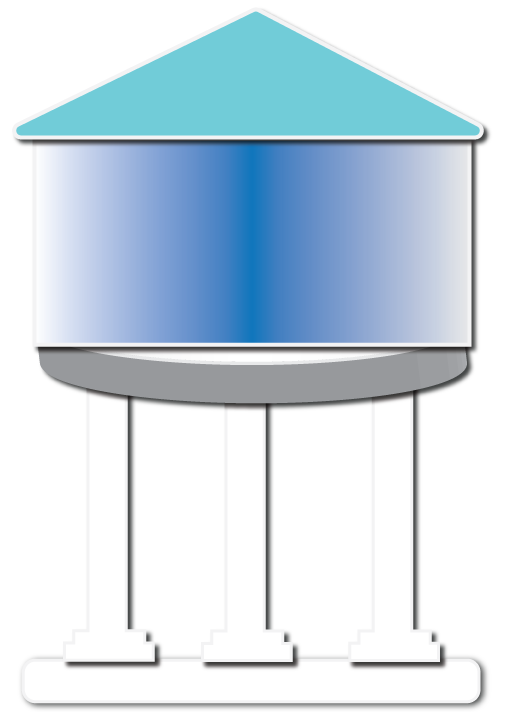
Any fixed-head boundary — a spring intake, borehole, or storage reservoir. Every network needs at least one. Its water level sets the starting hydraulic head.
Break Pressure Tank
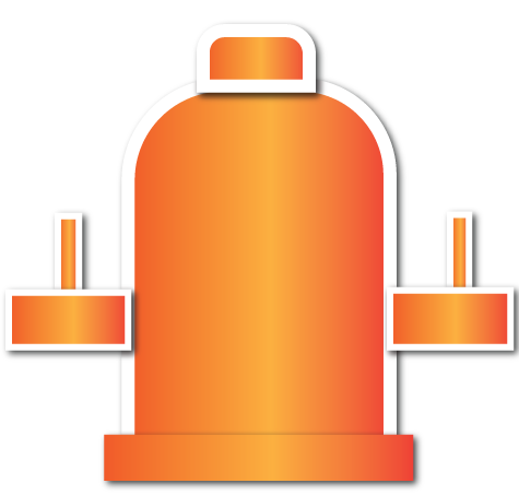
A mid-network tank that resets the hydraulic grade line to its own water level. Use it to tame excess static pressure on steep terrain. Sources and BPTs both have an optional Tank Volume field, checked against a recommended storage size.
Junction
A demand point — a tapstand or cluster of consumers. Give it a population, and GravityFlow works out its design demand automatically.

Pipe
Connects two nodes. Has a diameter, material, Hazen‑Williams C‑factor, and optional fittings (minor losses) — these are what you tune to fix warnings.
Pressure Reducing Valve
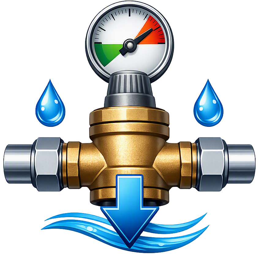
Throttles down to hold a fixed residual pressure just downstream, whatever the arriving head. Unlike a BPT it has no storage — if arriving head ever drops below its target, it passes that lower pressure through instead.
Air Release Valve
A zero-demand pass-through marker for a local high point along a pipe run, where trapped air needs relief. GravityFlow suggests one automatically wherever it finds one.
Scour / Washout Valve
Another zero-demand pass-through marker, for a low point or dead end where sediment settles and periodic flushing is needed. Also suggested automatically.
Pump
Not a node — a switch you enable on any pipe. Lifts water using a simple curve (rated flow/head, shutoff head, efficiency), for boreholes, low-lying intakes, or a booster partway down a scheme.
3 Getting Started
From a blank map to your first calculated network.
- Start a project.Click New Project in the top bar and fill in the basics — name, village, current population. You'll be asked where to save; pick any folder on your computer.
- Check feasibility first.Click Feasibility Analysis and enter your source's tested dry-season yield. This confirms the source can actually supply your design population before you spend time drawing pipes.
- Place your Source.Select the Source tool in the left toolbar and click its real location on the map. Set its ground elevation and water level in the Properties panel (use the Fetch button to pull real elevation data automatically).
- Add Junctions and Pipes.Place a Junction for each tapstand/demand point, set its population, then use the Pipe tool to connect everything back to the Source, branch by branch.
- Insert a BPT if needed.If a pipe's static pressure would exceed its pressure class on steep ground, add a Break Pressure Tank partway down to reset the head.
- Hit Calculate.GravityFlow solves the whole network instantly and lists every warning, with a suggested fix for each one.
- Iterate.Resize a pipe, move a BPT, adjust a water level — then Calculate again. Try Auto-Size or Optimize for a quick first pass, then fine-tune by hand.
4 Toolbar Reference
The left-hand tool rail, top to bottom.

5 Sidebar Panels
The right-hand rail — click any icon to open its panel.
| Panel | What it's for |
|---|---|
| Properties | Edit whatever node or pipe is currently selected — elevation, water level, population, diameter, material, a pump curve on a pipe, and more. |
| Network | Sortable tables of every node and pipe in the project — click a row to jump to it on the map. |
| Results | Summary totals, all warnings with suggested fixes, and full Node/Pipe results tables. Appears after you click Calculate. |
| BOQ | Bill of Quantities — pipe lengths and structure counts grouped automatically, plus a Labor / Crew Rates section for construction work items, each with an editable Unit Price and a running Grand Total. |
| Profile | A longitudinal ground/HGL profile from the Source down to any junction or BPT you pick — the fastest way to see where pressure gets tight. |
| Layers | Toggle visibility of node types and of pipes by diameter, so a busy network stays readable. |
| Settings | Demand defaults (LPCD, peak factor), design velocity/pressure targets, default pipe material, and what shows up when you hover the map. |
| Basemap | Switch between satellite imagery, street maps, topographic maps, and hillshade terrain (click anywhere on hillshade to read that point's elevation). |
| Labels | One switch to show or hide node labels on the map. |
BOQ Labor / Crew Rates
Alongside the pipe and structure quantities, the BOQ tab includes a Labor / Crew Rates table for the construction work itself — trenching, pipe laying, backfilling, and structure-building crews. Both Qty and Unit Price are editable: quantity starts out auto-filled from your network (total pipe length, node counts) and rate starts out pre-filled with a generic reference figure, but you can override either — useful if, say, part of the trench run is through rock and needs a different rate than the rest, or you simply want to split one line into two. If your network includes any pump-enabled pipes, a separate Pumps table appears too, with one row per pump and an estimated power draw (kW) — from the actual calculated flow once you've run Calculate, or the rated duty point as a placeholder before that.
| Work item | Unit | Default rate | Quantity source |
|---|---|---|---|
| Trench excavation (manual) | m | $2.50 | Total pipe length |
| Pipe laying & jointing | m | $1.50 | Total pipe length |
| Backfilling & reinstatement | m | $1.00 | Total pipe length |
| Source / intake structure construction crew | no. | $150 | Number of Source nodes |
| BPT construction crew | no. | $120 | Number of BPT nodes |
| PRV chamber & valve installation crew | no. | $100 | Number of PRV nodes |
| Junction / tapstand construction crew | no. | $80 | Number of Junction nodes |
| Air Release Valve chamber installation crew | no. | $90 | Number of ARV nodes |
| Scour/Washout Valve chamber installation crew | no. | $90 | Number of Scour nodes |
| Pump set installation & electrical connection crew | no. | $200 | Number of pump-enabled pipes |
| Testing & commissioning crew | lump sum | $300 | Once per project |
| Mobilization & site clearance crew | lump sum | $200 | Once per project |
6 How the Math Works
The hydraulics engine, in plain terms.
GravityFlow computes headloss with the Hazen‑Williams equation, the industry standard for gravity and municipal water networks:
Velocity then comes straight from the continuity equation, V = Q / A —
notice that velocity depends only on flow and pipe diameter, never directly on how
much elevation drop you have. Extra head doesn't make water move faster; it either gets consumed as
friction loss, or shows up as residual pressure downstream (or gets absorbed by a BPT).
Elevation, HGL and Pressure
These three numbers are the heart of every result GravityFlow shows you:
- Elevation — the ground level at a node (from Fetch, or entered manually).
- HGL (Hydraulic Grade Line) — the height water would rise to at that point, starting from the Source's water level and falling by the headloss of every pipe along the way.
- Pressure — simply
HGL − Elevation. This is what the pipe network actually delivers to a tapstand.
A Break Pressure Tank is the one place this chain breaks deliberately: instead of inheriting the arriving HGL, a BPT resets it to its own water level — which is exactly how you tame a network that would otherwise blow past a pipe's pressure rating on steep ground.
Pipe Materials
Every pipe carries a material, which sets its Hazen‑Williams C‑factor — a roughness rating from 60 (very rough) to about 160 (glass‑smooth). A higher C means a smoother bore, which means less friction headloss for the same flow and diameter — look back at the formula above and notice C sits in the denominator, raised to the 1.852 power, so even a modest difference in C changes headloss noticeably.
| Material | Default C | Typical use | Notes |
|---|---|---|---|
| HDPE (High-Density Polyethylene) | 150 | Default choice for buried rural gravity mains | Smooth bore that stays smooth for decades, flexible enough to snake around obstacles, welded/fused joints resist leaks better than any other option here — the standard pick unless you have a specific reason not to. |
| uPVC (unplasticized PVC) | 150 | Buried mains, especially where HDPE isn't locally available | Same hydraulic performance as HDPE, but rigid — needs more bends/fittings on uneven ground, and its solvent-welded or push-fit joints are less forgiving of ground movement than HDPE's fusion joints. |
| GI (Galvanized Iron) | 100 | Short exposed/above-ground runs — river crossings, wall penetrations, tapstand risers | Noticeably rougher than plastic (and gets rougher with age as the galvanizing wears and the bore corrodes), so the same pipe carries less flow for a given headloss budget — but it survives UV, impact and vandalism that would split a plastic pipe. |
| DI (Ductile Iron) | 130 | High-pressure trunk mains, road/river crossings needing extra strength | Sits between plastic and GI on roughness, but its real advantage is mechanical: much higher pressure and impact ratings than any pipe material here, at a higher cost — reach for it where a pipe must survive traffic loading or very high static head, not for routine distribution. |
Minor Losses (Fittings)
Friction along the pipe wall isn't the only thing that costs head — every bend, tee and valve adds a small extra loss too, from the turbulence of water changing direction or squeezing through a valve body. GravityFlow adds these as an optional minor loss on top of the Hazen‑Williams friction loss, using the standard resistance‑coefficient method:
Open a pipe's Properties panel and scroll to Fittings (minor losses) to enter counts for 90° elbows, 45° elbows, branch tees, gate valves and check valves — GravityFlow sums their K‑values and folds the result straight into that pipe's total headloss and the network's pressure calculations. Leave every count at zero (the default) to ignore minor losses entirely, which is a reasonable simplification for long straight rural mains where friction dominates; it's worth turning on for shorter pipes with several fittings, where minor losses can be a meaningful share of the total.
Tank Storage Sizing
Pressure and velocity are about the network's instant behavior, but a Source or BPT's tank also needs enough volume to balance demand over the course of a day — supply rarely matches consumption minute-for-minute, and the tank absorbs the difference. GravityFlow suggests a minimum tank volume for every Source and BPT, based on everything downstream of it:
Note this uses each junction's average daily demand (population × LPCD), not the peaked design flow used for pipe sizing — storage is about the day's total volume, not its busiest instant. Enter a Tank Volume on any Source or BPT to compare it against this recommendation; if it's undersized, Calculate adds a warning. The 25% storage factor is a common rule-of-thumb starting point for rural balancing tanks, not a fire-flow or emergency reserve figure — adjust it under Settings › Design Criteria › Tank storage factor if your design standard calls for something different, and leave the Tank Volume field blank on any node where storage isn't relevant (e.g. a spring intake with no real holding tank).
Pumps
Enable Pump on any pipe's Properties panel to lift water instead of just losing head to friction — for a borehole/tubewell source, a low-lying river intake, or a booster partway down a scheme. The head a pump adds depends on how much flow is passing through it, following a simple parabolic curve through two points you provide: the shutoff head (what it would push against zero flow) and a rated duty point (head at its rated flow):
That head is added on top of the normal Hazen‑Williams walk down the network — the same friction loss still applies along the pump's own pipe, it just starts from a boosted head rather than the source's raw water level. Because flow through every pipe in a branched tree is already fixed by downstream demand (no iteration needed to find the pump's operating point), GravityFlow can read the head straight off this curve at the pipe's calculated flow. An Efficiency (%) field converts that hydraulic work into an electrical power estimate (shown in the Results tab and the BOQ's Pumps table):
Air Release & Scour Valves
Calculate scans the finished network for two situations and suggests a fix, the same way it suggests a pipe upsize for low pressure:
- A node sitting higher than both its upstream neighbor and every downstream neighbor — a local summit along the pipe run, where air can collect and block flow — gets an Air Release Valve suggestion.
- A node sitting lower than its upstream neighbor, and either a dead end or lower than every downstream neighbor too — a low point or dead end where sediment settles — gets a Scour/Washout Valve suggestion.
These are suggestions, not automatic placements: GravityFlow can tell you where, but only you can draw the actual ARV/Scour node in. Once a node is typed as ARV or Scour, it's treated as already addressed and won't be suggested again. This check only looks at node elevations along the tree — it can't spot a summit or sag hiding partway along a single long pipe between two nodes, since pipe bends don't carry their own elevation data.
7 Worked Examples
Five real networks, captured straight from the app — real satellite imagery, real icons, real calculated results. The first four all follow one realistic 1,300-person hillside scheme through different stages of the design process; the fifth is a focused troubleshooting walkthrough.
Example 1 · A Realistic Village Supply
LayoutA single hillside reservoir feeding three branches of tapstands through one Break Pressure Tank — this is what a genuine small-scheme layout looks like once it's past the "toy example" stage. Real elevations were pulled straight from the Elevation tool.
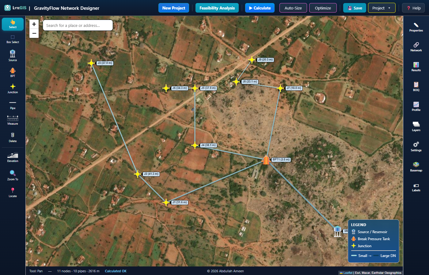
The full scheme, fit to view, with the Legend confirming every node type present.
Here's the complete calculated output behind that picture — every node's elevation, HGL and residual pressure, and every pipe's length, diameter, flow and velocity. This is exactly what the Results tab shows after you hit Calculate.
| Node | Elev (m) | HGL (m) | Pressure (m) | Status |
|---|---|---|---|---|
| SRC1 | 1723.0 | 1725.00 | 2.00 | ok |
| BPT1 | 1667.0 | 1669.00 | 2.00 | ok |
| J1 | 1632.0 | 1663.57 | 31.57 | ok |
| J2 | 1619.0 | 1660.31 | 41.31 | ok |
| J3 | 1613.0 | 1650.04 | 37.04 | ok |
| J4 | 1627.0 | 1665.14 | 38.14 | ok |
| J5 | 1622.0 | 1659.89 | 37.89 | ok |
| J6 | 1622.0 | 1656.33 | 34.33 | ok |
| J7 | 1648.0 | 1665.96 | 17.96 | ok |
| J8 | 1637.0 | 1660.12 | 23.12 | ok |
| J9 | 1637.0 | 1657.50 | 20.50 | ok |
| Pipe | Length (m) | DN (mm) | Flow (L/s) | Velocity (m/s) | Headloss (m) | Status |
|---|---|---|---|---|---|---|
| P1 (SRC1→BPT1) | 392.5 | 63 | 1.743 | 0.56 | 2.141 | ok |
| P2 (BPT1→J1) | 422.3 | 40 | 0.839 | 0.67 | 5.427 | ok |
| P3 (J1→J2) | 157.0 | 32 | 0.604 | 0.75 | 3.260 | ok |
| P4 (J2→J3) | 467.3 | 25 | 0.326 | 0.66 | 10.271 | ok |
| P5 (BPT1→J4) | 282.6 | 32 | 0.482 | 0.60 | 3.858 | ok |
| P6 (J4→J5) | 222.4 | 25 | 0.339 | 0.69 | 5.256 | ok |
| P7 (J5→J6) | 110.8 | 15 | 0.104 | 0.59 | 3.554 | ok |
| P8 (BPT1→J7) | 283.5 | 32 | 0.423 | 0.53 | 3.043 | ok |
| P9 (J7→J8) | 173.3 | 20 | 0.228 | 0.73 | 5.835 | ok |
| P10 (J8→J9) | 104.7 | 15 | 0.091 | 0.52 | 2.621 | ok |
Notice the pattern: pipes get smaller the further they sit from the Source (63→40→32→25 mm down the J1–J3 branch), because each one only has to carry what's left of the flow after everything upstream of it has already branched off.
Example 2 · Taming Steep Terrain with a BPT
Why the BPT is thereThe same scheme drops 56 m from the Source (1723 m) down to BPT1 (1667 m) alone, and keeps falling to around 1613 m at the lowest junction. Left unchecked, that's well over a standard PN10 pipe's 102 m pressure rating — Example 4 shows exactly what that looks like. BPT1 resets the hydraulic grade line right where the slope steepens, so every pipe below it only ever sees a fraction of that static head.
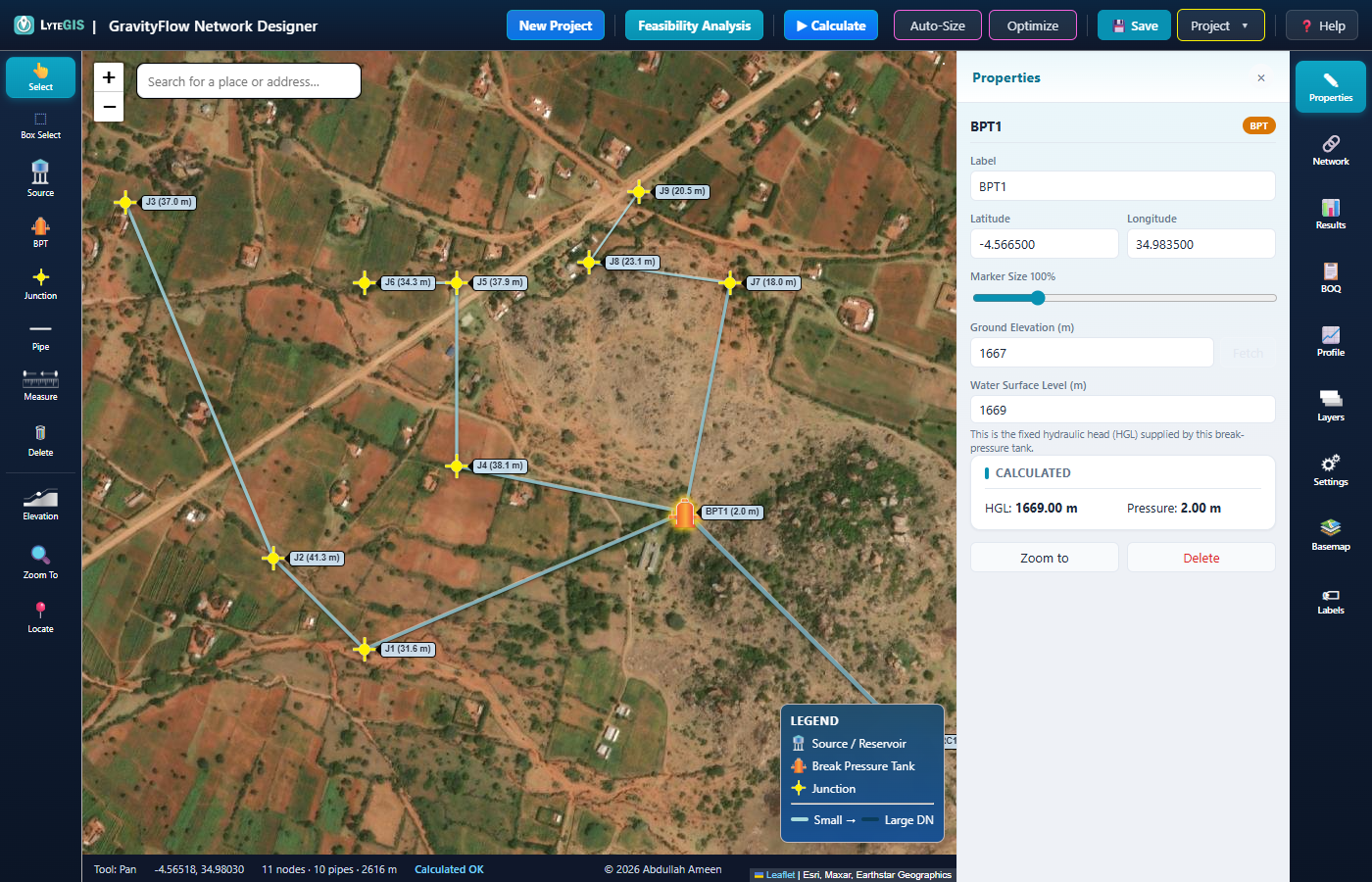
BPT1's Properties panel — water level fixed at 1669 m regardless of what arrives from upstream.
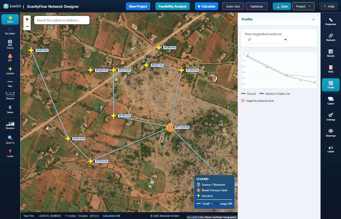
The Profile tab, Source→J7: the HGL (blue, dashed) visibly resets at BPT1 instead of continuing to fall with the ground.
The pipe straight out of BPT1's reset water level (1669 m) is what every downstream branch actually has to work with — not the Source's original 1725 m:
| Pipe | Route | Length (m) | DN (mm) | Headloss (m) | PN10 rating |
|---|---|---|---|---|---|
| P1 | SRC1 → BPT1 | 392.5 | 63 | 2.14 | 102 m — fine, arrives with head to spare |
| P2 | BPT1 → J1 | 422.3 | 40 | 5.43 | 102 m — well inside |
| P5 | BPT1 → J4 | 282.6 | 32 | 3.86 | 102 m — well inside |
| P8 | BPT1 → J7 | 283.5 | 32 | 3.04 | 102 m — well inside |
Every branch starts fresh from BPT1's 1669 m, not the Source's 1725 m — that's the entire point of resetting the HGL. Compare this table with Example 4's, where these same branches connect straight to the Source instead.
Example 3 · Gentle Terrain: No BPT Needed
ContrastA BPT is a fix for a specific problem — too much static head — not something every scheme needs by default. This small village sits on a much gentler slope: only 24 m of elevation drop across the whole network, well inside any standard pipe's pressure rating, so a single Source feeding two simple branches is all it takes.
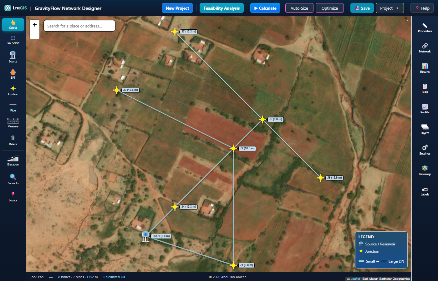
Notice the Legend has no "Break Pressure Tank" row at all — none exists in this project.
| Node | Elev (m) | HGL (m) | Pressure (m) | Status |
|---|---|---|---|---|
| SRC1 | 1656.0 | 1658.00 | 2.00 | ok |
| J1 | 1650.0 | 1656.80 | 6.80 | ok |
| J2 | 1644.0 | 1654.53 | 10.53 | ok |
| J3 | 1640.0 | 1652.58 | 12.58 | ok |
| J4 | 1644.0 | 1657.25 | 13.25 | ok |
| J5 | 1644.0 | 1652.82 | 8.82 | ok |
| J6 | 1635.0 | 1648.88 | 13.88 | ok |
| J7 | 1632.0 | 1645.26 | 13.26 | ok |
| Pipe | Length (m) | DN (mm) | Flow (L/s) | Velocity (m/s) | Headloss (m) | Status |
|---|---|---|---|---|---|---|
| P1 (SRC1→J1) | 175.3 | 32 | 0.332 | 0.41 | 1.201 | ok |
| P2 (J1→J2) | 222.4 | 25 | 0.215 | 0.44 | 2.264 | ok |
| P3 (J2→J3) | 248.0 | 20 | 0.104 | 0.33 | 1.959 | warn |
| P4 (SRC1→J4) | 78.5 | 32 | 0.397 | 0.49 | 0.749 | ok |
| P5 (J4→J5) | 235.5 | 25 | 0.299 | 0.61 | 4.436 | ok |
| P6 (J5→J6) | 157.0 | 15 | 0.091 | 0.52 | 3.931 | ok |
| P7 (J5→J7) | 235.5 | 15 | 0.104 | 0.59 | 7.552 | ok |
P3 is the one exception — 0.33 m/s, just under the 0.4 m/s target, on the tail end of the J1–J3 branch. Pressure everywhere is nowhere near the 5–70 m limits either direction, which is exactly what "plenty of margin, no BPT required" looks like in the numbers.
Example 4 · Steep Terrain Without a BPT
What goes wrongThis is Example 2's exact layout and elevations — same Source, same three branches, same pipe sizes — with only one thing changed: BPT1 removed, so every branch connects straight back to the Source. Nothing else was touched.
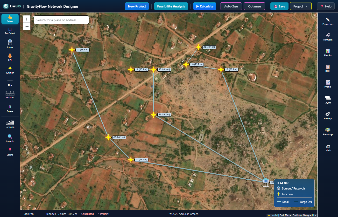
Same shape, same site — but the status bar now reads "Calculated — 4 issue(s)" in red.
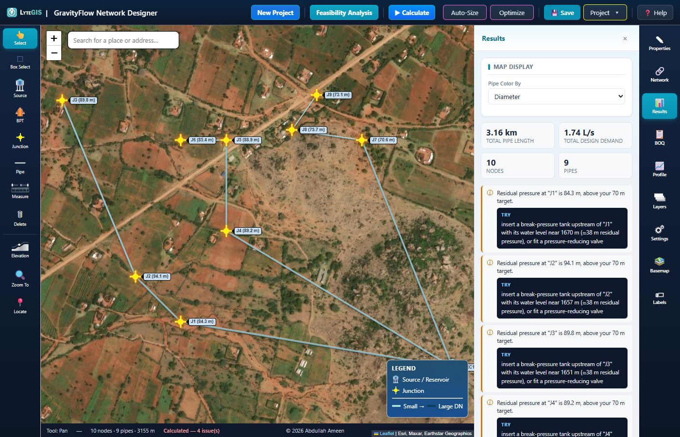
The Results panel, unedited: every junction blows past the 70 m pressure target, and four pipes exceed their PN10 rating. Read the suggested fix — the app arrives at the same answer Example 2 already used.
Compare this node table directly with Example 1's — same elevations, same population, same pipe sizes, only the BPT is gone:
| Node | Elev (m) | HGL (m) | Pressure (m) | Status |
|---|---|---|---|---|
| SRC1 | 1723.0 | 1725.00 | 2.00 | ok |
| J1 | 1632.0 | 1716.33 | 84.33 | high |
| J2 | 1619.0 | 1713.08 | 94.08 | high |
| J3 | 1613.0 | 1702.80 | 89.80 | high |
| J4 | 1627.0 | 1716.17 | 89.17 | high |
| J5 | 1622.0 | 1710.91 | 88.91 | high |
| J6 | 1622.0 | 1707.36 | 85.36 | high |
| J7 | 1648.0 | 1718.57 | 70.57 | high |
| J8 | 1637.0 | 1712.74 | 75.74 | high |
| J9 | 1637.0 | 1710.12 | 73.12 | high |
| Pipe | Route | Length (m) | DN (mm) | Velocity (m/s) | Headloss (m) | Status |
|---|---|---|---|---|---|---|
| P1 | SRC1→J1 | 674.3 | 40 | 0.67 | 8.665 | ok |
| P2 | J1→J2 | 157.0 | 32 | 0.75 | 3.260 | danger |
| P3 | J2→J3 | 467.3 | 25 | 0.66 | 10.271 | danger |
| P4 | SRC1→J4 | 646.9 | 32 | 0.60 | 8.831 | ok |
| P5 | J4→J5 | 222.4 | 25 | 0.69 | 5.256 | danger |
| P6 | J5→J6 | 110.8 | 15 | 0.59 | 3.554 | danger |
| P7 | SRC1→J7 | 598.5 | 32 | 0.53 | 6.426 | ok |
| P8 | J7→J8 | 173.3 | 20 | 0.73 | 5.835 | ok |
| P9 | J8→J9 | 104.7 | 15 | 0.52 | 2.621 | ok |
Every pressure figure roughly triples compared with Example 1 — J2 alone jumps from 41.31 m to 94.08 m. The four danger pipes are the ones whose lowest point sits far enough below the Source that static pressure (no flow at all, worst case) exceeds their PN10 rating of 102 m — note the velocities and headloss barely changed from Example 1's table, since diameters are identical. Only the missing BPT changed.
Example 5 · Fixing a Low-Velocity Warning
TroubleshootingBack to Example 1's scheme. Tail-end branches with very small flow are the most common source of a "Low velocity — risk of sedimentation" warning — here's the exact before/after of spotting and fixing one on pipe P10 (the last few metres of pipe out to J9).
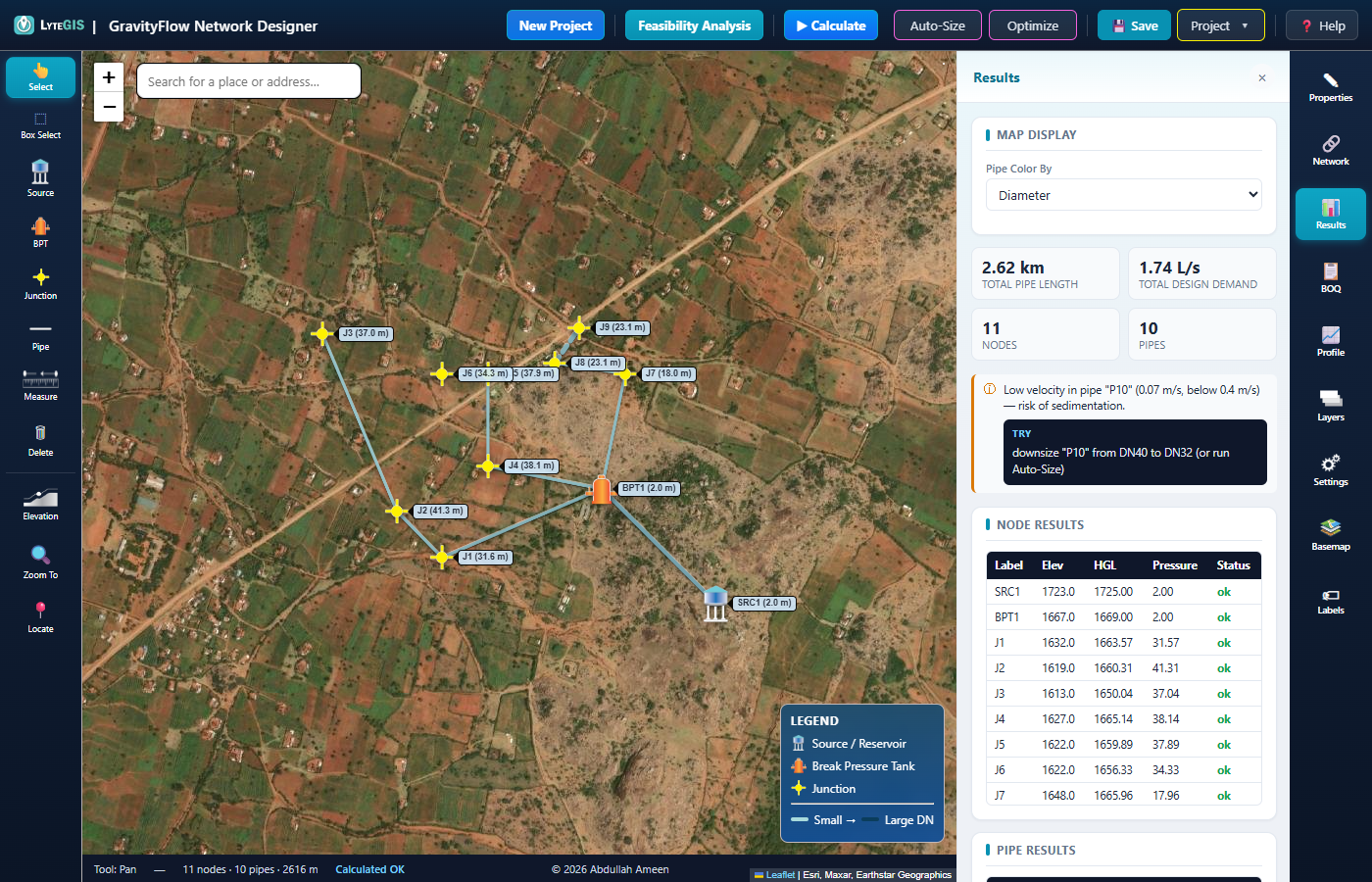
P10 oversized to DN40: velocity collapses to 0.07 m/s and the warning names the exact fix.
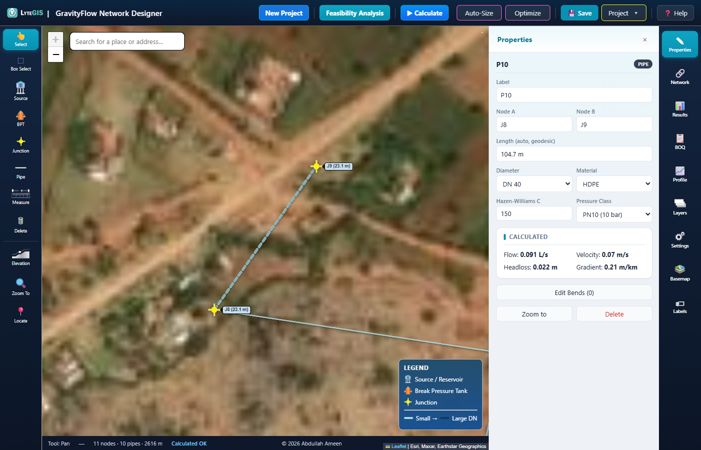
Zoomed into P10's own Properties panel — Diameter and Calculated Velocity sit right next to each other.
- Read the warningIt names the pipe and its current velocity, and suggests exactly which standard size to switch to.
- Open the pipe's PropertiesStep its Diameter down to the suggested size — here, DN40 down to DN15.
- RecalculateConfirm the warning clears, and that pressure downstream didn't suffer as a side effect.
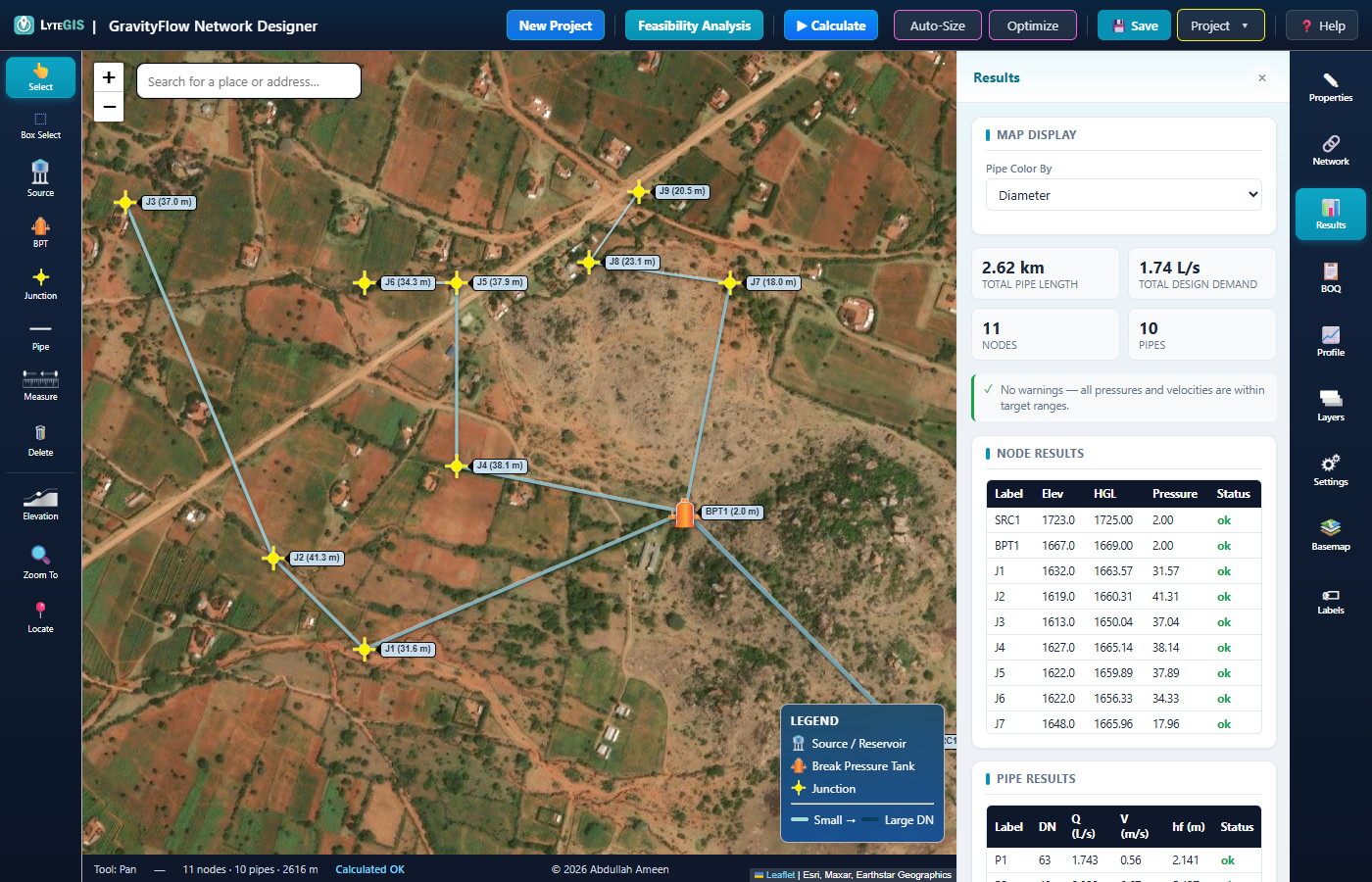
P10 back at its correct DN15 — "No warnings", every node and pipe status green.
P10 carries J9 alone — the very last few metres of the network, population 70. Same flow both times; only the diameter changes:
| State | DN (mm) | Flow (L/s) | Velocity (m/s) | Headloss (m) | Status |
|---|---|---|---|---|---|
| Before (oversized) | 40 | 0.091 | 0.07 | 0.022 | warn |
| After (correct) | 15 | 0.091 | 0.52 | 2.621 | ok |
Same 0.091 L/s both rows — the flow never changed, only the pipe it's squeezed through. A wider pipe (DN40) barely trickles at 0.07 m/s and loses almost no head to friction (0.022 m); the narrower, correct DN15 speeds it up to a healthy 0.52 m/s, at the cost of more headloss (2.621 m) — head this branch could easily spare, per Example 1's table.
8 Saving & Files
Where your work lives, and how to keep it safe.
Auto-save + linked files
Every change is auto-saved in your browser as a safety net. But the real, durable copy of your project
is a plain .json file — link one via New Project, Open
Project, or the Save button, and GravityFlow keeps writing your changes
into it automatically from then on.
The Save button
Click Save (or press Ctrl+S) any time you want to force an immediate write. If no file is linked yet, it asks you where to save one and links it for you.
Reconnecting after a refresh
Browsers don't let a web page silently keep file access across a reload. GravityFlow works around this two ways:
- If you had a file linked, it tries to silently reconnect on load — or shows a one-click "Resume editing" prompt if the browser needs you to reconfirm access.
- If you were only relying on the browser's auto-save (no file linked), you'll see an "Unsaved session found" prompt with Open / Discard options.
Exporting
Use the Project menu for one-off exports: Export JSON (a portable copy of the whole project), Export CSV (raw results for spreadsheets), Export KML (open your network in Google Earth), Export EPANET (.inp) (open the same network in EPANET for a second, independent hydraulic check), or Print Report (a full, formatted design report — including the BOQ — ready to save as PDF).
Importing GPS Waypoints & Tracks (GPX)
If you've surveyed with a handheld GPS unit or a phone app, use Project › Import GPX… to bring that data in. GravityFlow reads both kinds of GPX content in one go:
- Waypoints (
<wpt>) — individual GPS'd points, such as a source, tank, or tapstand location — become purple reference pins, each showing its name, coordinates, and elevation if the file has one. - Tracks (
<trk>) — a path you walked, such as the pipe route itself — become a dashed purple reference line, showing its total length and point count.
Both are reference only — importing a GPX file never creates a Source, BPT, Junction, or Pipe by itself. Click a pin or line for its details and a Remove button, then use the normal Source/BPT/Junction/Pipe tools to place the real network element at (or along) that spot. Both are saved with your project like everything else, so they'll still be there next time you open it — clear the ones you no longer need as you trace over them.
Civil 3D Interoperability (LandXML)
GravityFlow can't open a native Civil 3D .dwg file directly — that's a proprietary binary
format with Civil 3D-specific object types, and reading it would require a paid SDK. The practical
bridge both ways is LandXML, an open XML format Civil 3D natively imports and exports
(Insert › Import LandXML, or right-click Points/Pipe Networks in Toolspace).
- GravityFlow › Civil 3D: Project › Export LandXML (Civil 3D) writes every node as a survey point and the whole network as a LandXML Pipe Network (structures + pipes with diameter/material), georeferenced as WGS84 geographic coordinates. Bring it into Civil 3D with Import LandXML.
- Civil 3D › GravityFlow: Project › Import LandXML… reads a LandXML file's points, pipe network structures, and pipes back in as reference pins/lines — the same reference-only overlay GPX import uses, for the same reason (see above).
<CoordinateSystem> isn't WGS84
geographic or a recognizable UTM zone, GravityFlow has no way to know
where on Earth those coordinates belong and will refuse the import rather than place it somewhere
wrong — assign a real coordinate system to the Civil 3D drawing before exporting if you hit this.Pipe "invert" in the exported LandXML uses each node's ground elevation as an approximation — GravityFlow doesn't model a separate invert depth below the structure.
9 Keyboard Shortcuts
| Key | Action |
|---|---|
| Esc | Cancel the current draw/edit action and return to the Select tool. |
| Enter | Finish the current Measure while the Measure tool is active. |
| Delete / Backspace | Remove everything currently highlighted by Box Select. |
| Ctrl+S | Save the project immediately. |
| Ctrl+Z | Undo the last node/pipe edit (also the ↶ button in the top bar). |
| Ctrl+Y | Redo (also the ↷ button). Any new edit after an undo clears the redo history. |
10 Troubleshooting & FAQ
"Loop detected" error
Gravity networks in GravityFlow must be a branched tree — no pipe may reconnect two paths that both lead back to the same Source. Remove one of the pipes forming the loop.
"BPT may not fill" warning
The head arriving at that Break Pressure Tank is below its ground elevation, so it physically can't fill. Either lower the BPT's site, raise the upstream Source's water level, or upsize the pipe feeding it to cut headloss.
Negative pressure at a junction
Water can't physically reach that point at all — this is always a danger-level warning. Click it for a suggested fix: upsize the bottleneck pipe, raise the upstream water level, or relocate the junction to lower ground.
Why does the map need internet access?
Satellite/street/topographic basemaps, the terrain hillshade layer, the elevation Fetch button, and the place search box all call external map/elevation services and need a connection. Everything else — drawing, calculating, saving, exporting, printing — works completely offline.
Auto-Size made everything worse — why?
Auto-Size only optimizes for velocity; it has no idea what that does to downstream pressure, and can oversize or undersize a pipe if flows are very small. Use it for a rough first pass, then check the Results tab and fine-tune diameters by hand — or try Optimize, which specifically hunts for the pressure bottleneck instead.
What's the difference between a Source and a BPT?
Both have a fixed water level that governs head. A Source is where water enters the network for the first time (a real intake/reservoir). A Break Pressure Tank is a mid-network structure whose only job is to reset the HGL — think of it as a deliberate pressure "circuit breaker" partway down a steep slope.
My source is a borehole/tubewell — can I model that?
Yes — enable Pump on the pipe leaving your Source (the Source's water level then represents the sump/wet-well level, not the delivered pressure). There's no separate "Pump Station" node; the pump lives on the pipe itself, so it works equally well as a booster mid-scheme, not just at the very start.
Why is GravityFlow suggesting an Air Release or Scour Valve here?
Calculate flags local high points (candidate Air Release Valves, to relieve trapped air) and local low points/dead ends (candidate Scour/Washout Valves, for periodic flushing) purely from node elevations along the tree. It's only a suggestion — add the node yourself if you agree, or ignore it if the site doesn't call for one. Once a node is typed as ARV or Scour, it stops being suggested.